Rating:
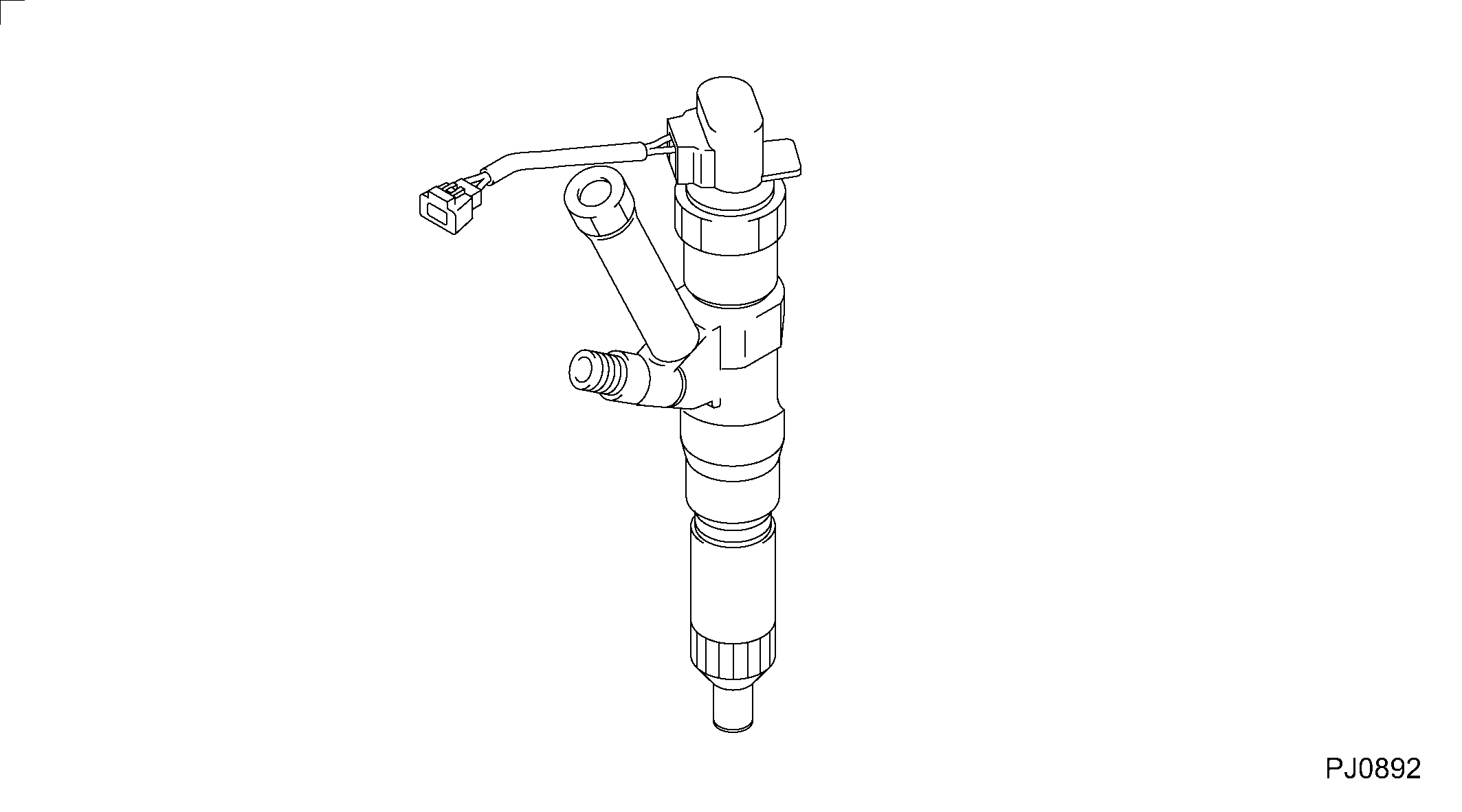
Information injector assy Denso
Compare Prices: .
As an associate, we earn commssions on qualifying purchases through the links below
XJMiao 1pcs Injector 095000-0402, 095000-0403, 095000-0404, 23910-1163, 23910-1164, S2391-01164 Compatible with Hino Trucks P11C Engine
XJMiao Provides smooth engine operation. || Improved engine starting performance. || Reduce noise and vibration. || Fast response for improved acceleration performance. || Reduce engine maintenance costs.
Injector Compatible with Hino Trucks P11C Engine Models 095000-0402 095000-0403 095000-0404 23910-1163 23910-1164 S2391-01164
LFBsZC Compatible with multiple models including 095000-0402, 095000-0403, 095000-0404, and 23910-1163, ensuring versatility Compatible With your needs. || Designed specifically Compatible With Hino Trucks P11C Engine, providing reliable performance Compatible With your vehicle. || engineered components effective fuel injection Compatible With optimized engine efficiency. || Easy installation process reduces downtime, allowing you to get back on the road faster. || construction offers under various driving conditions.
Fuel Injector Fits for HINO P11C Engine (Pack of 1) 095000-0402 095000-0403 095000-0404 23910-1163 23910-1164 S2391-01164
GSHLGAO Part Number:095000-0402 095000-0403 095000-0404 23910-1163 23910-1164 S2391-01164 || Application:Fits for HINO P11C Engine || Attention: The application information presented is intended for guidance purposes. It is recommended to verify the part number and conduct a comparison with the existing parts prior to making a purchase. Should you have any inquiries, please do not hesitate to reach out to us. || This product offers exceptional value with its reliable performance, ease of installation, and quick response time. It is a solid choice for those seeking a dependable and efficient solution.
Include in ##:
Cross reference number
Part num
Firm num
Firm
Name
09500-00404
S2391-0116
INJECTOR ASSY
Information:
1. Make a mark on compressor housing (1), cartridge assembly (3) and the turbine housing (4) for correct installation. 2. Loosen clamp assembly (2). Remove compressor housing (1) and cartridge assembly (3) from the turbine housing.3. Remove bolts (6) and plates (5) that hold cartridge assembly in the compressor housing. Remove cartridge assembly (3). 4. Remove O-ring seal (7) from the cartridge assembly. 5. Put cartridge assembly (3) in position in tooling (A) and loosen nut on the compressor wheel with tooling (C).6. Remove nut (8) and the compressor wheel (9). 7. Remove shaft and wheel assembly (10) from the cartridge assembly. 8. Remove shroud (11) from the cartridge assembly. 9. Remove four bolts (12) and then remove backplate (13) from the cartridge assembly.10. Remove spacer (14) from the backplate. 11. Remove two seal rings (15) from the spacer. 12. Remove snap ring (16) from cartridge housing with tool (B). 13. Remove bearing (17) and rings from the cartridge housing.14. Remove snap ring (18) from cartridge housing with tool (B). 15. Turn the cartridge housing over and then remove screws (20), plate (21) and collar (19). 16. Remove bearing (22) from the cartridge housing. 17. Remove snap ring (23) from the cartridge housing with tool (B).Assemble Turbocharger
Make sure all of the oil passages in the turbocharger cartridge housing are clean and free of dirt and foreign material. Put clean engine oil on all parts of the cartridge assembly. 1. Install snap ring (1) in the cartridge housing with tool (A). Make sure the oil hole in plate (5) is open and clean to prevent a bearing failure.2. Install bearing (2), collars (3), plate (5) and screws (4). Tighten the screws to a torque of 2.5 N m (22 lb.in.). Install the rings that hold bearings in position with the round edges of the rings toward the bearings. 3. Turn the cartridge housing over. Install snap ring (6) in the cartridge housing with tool (A). Install bearing (7), ring (8) and ring (9) in the housing. Install snap ring (10) with tool (A). Put 6V2055 High Vacuum Grease in the grooves for seal rings (11) at assembly to one half or more of the depth of the groove all the way around the grooves. 4. Install seal rings (11) on spacer (12). 5. Install spacer (12) in the backplate.6. Put the backplate (13) in position on the cartridge housing and install the bolts that hold it. Tighten the bolts to a torque of 9.5 N m (84 lb.in.). 7. Put the shroud (14) in position on the cartridge housing. 8. Install shaft and wheel assembly (15) in the cartridge housing. 9. Put the cartridge assembly in position in tooling (B).10. Put a small amount of oil on the wheel face that will be under the nut.11. Put compressor wheel (17) in position on the shaft.
Do not put a side force on the shaft when the nut is tightened.
12. Install nut (16) and tighten it to a torque of 4